使用Platformio平台的libopencm3开发框架来开发STM32G0,下面介绍SD卡模块的使用方法。
1 新建项目
- 在PIO主页新建项目spi_sdcard,框架选择libopencm3,开发板选择 MonkeyPi_STM32_G070RB;
- 新建完成后在src目录新建主程序文件main.c;
- 然后更改项目文件platformio.ini的烧写和调试方式:
upload_protocol = cmsis-dap
debug_tool = cmsis-dap
2 编写程序
2.1 加入FATFS库
- 从网站fatfs http://elm-chan.org/fsw/ff/00index_e.html 下载最新的源码;
- 工程目录lib下新建fatfs文件夹;
- 然后将fatfs源码的source目录下所有文件放置到工程的lib\fatfs目录下;
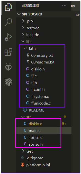
- 将diskio.c文件移动到src目录下,这个文件是需要我们实现的底层接口;
2.2 实现SPI接口的SD读写
在src目录下新建spi_sd.h 和 spi_sd.c 文件,现在目录结构如下:

- spi_sd.h 头文件
/**
 * @file spi_sd.h
 * @author MakerInChina (makerinchina.cn)
 * @brief
 * @version 0.01
 * @date 2022-09-18
 *
 * @copyright Copyright (c) 2022
 *
 */

#ifndef _SPI_SD_HEAD_H_
#define _SPI_SD_HEAD_H_

#include <stdint.h>

/**
 * @brief init sd card
 *
 */
uint8_t spi_sd_init();

/**
 * @brief spi read sd
 *
 * @param buff
 * @param sector
 */
uint8_t spi_sd_read(uint8_t *buff, uint32_t sector);

/**
 * @brief spi write sd
 *
 * @param buff
 * @param sector
 */
uint8_t spi_sd_write(uint8_t *buff, uint32_t sector);

#endif //!_SPI_SD_HEAD_H_- spi_sd.c 实现
/**
 * @file spi_sd.c
 * @author MakerInChina (makerinchina.cn)
 * @brief
 * @version 0.01
 * @date 2022-09-18
 *
 * @copyright Copyright (c) 2022
 *
 */

#include "spi_sd.h"

#include <libopencm3/stm32/spi.h>
#include <libopencm3/stm32/gpio.h>

#define SDSPI    SPI1
#define SD_CS    GPIO4
#define SD_PORT  GPIOA

#define spi_cs_deselect()   gpio_set(SD_PORT, SD_CS)
#define spi_cs_select()     gpio_clear(SD_PORT, SD_CS)


/* Definitions for MMC/SDC command */
#define CMD0    (0x40+0)    /* GO_IDLE_STATE */
#define CMD1    (0x40+1)    /* SEND_OP_COND (MMC) */
#define ACMD41    (0xC0+41)    /* SEND_OP_COND (SDC) */
#define CMD8    (0x40+8)    /* SEND_IF_COND */
#define CMD9    (0x40+9)    /* SEND_CSD */
#define CMD10    (0x40+10)    /* SEND_CID */
#define CMD12    (0x40+12)    /* STOP_TRANSMISSION */
#define ACMD13    (0xC0+13)    /* SD_STATUS (SDC) */
#define CMD16    (0x40+16)    /* SET_BLOCKLEN */
#define CMD17    (0x40+17)    /* READ_SINGLE_BLOCK */
#define CMD18    (0x40+18)    /* READ_MULTIPLE_BLOCK */
#define CMD23    (0x40+23)    /* SET_BLOCK_COUNT (MMC) */
#define ACMD23    (0xC0+23)    /* SET_WR_BLK_ERASE_COUNT (SDC) */
#define CMD24    (0x40+24)    /* WRITE_BLOCK */
#define CMD25    (0x40+25)    /* WRITE_MULTIPLE_BLOCK */
#define CMD55    (0x40+55)    /* APP_CMD */
#define CMD58    (0x40+58)    /* READ_OCR */

#define CT_MMC 0x01 /* MMC ver 3 */
#define CT_SD1 0x02 /* SD ver 1 */
#define CT_SD2 0x04 /* SD ver 2 */
#define CT_SDC (CT_SD1|CT_SD2) /* SD */
#define CT_BLOCK 0x08 /* Block addressing */

static uint8_t spi_read_write8(uint32_t spi, uint8_t tx);
static uint8_t wait_ready(void);
static uint8_t send_cmd (uint8_t cmd,uint32_t arg);
static void set_spi_slow();
static void set_spi_fast();

/**
 * @brief init sd card
 *
 */
uint8_t spi_sd_init()
{
    uint8_t n, cmd, ty, ocr[4];
    uint16_t i;


    //init with low speed
    // set_spi_slow();

    spi_cs_select();

    for (n = 10; n; n--) spi_read_write8(SDSPI,0xff);    /* 80 dummy clocks */

    ty = 0;

    /* Enter Idle state */
    ty = send_cmd(CMD0, 0);

    // printf("  > enter idle:%d\n", ty);

    /* Initialization timeout of 1000 milliseconds */
    /* SDHC */

    if(ty == 1){

        if (send_cmd(CMD8, 0x1AA) == 1){ /* SDv2? */
        /* Get trailing return value of R7 response */
            for (n = 0; n < 4; n++) ocr[n] = spi_read_write8(SDSPI,0xff);
            /* The card can work at VDD range of 2.7-3.6V */
            if (ocr[2] == 0x01 && ocr[3] == 0xAA){
                /* Wait for leaving idle state (ACMD41 with HCS bit) */
                i=0xfff;
                while (--i && send_cmd(ACMD41, 1UL << 30));
                if (i && send_cmd(CMD58, 0) == 0){
                /* Check CCS bit in the OCR */
                    for (n = 0; n < 4; n++) ocr[n] = spi_read_write8(SDSPI,0xff);
                    ty = (ocr[0] & 0x40) ? CT_SD2 | CT_BLOCK : CT_SD2;

                }
            }
        }  else {    /* Not SDv2 card */
            // if (send_cmd(ACMD41, 0) <= 1)     {    /* SDv1 or MMC? */
            //     ty = CT_SD1; cmd = ACMD41;    /* SDv1 (ACMD41(0)) */
            // } else {
            //     ty = CT_MMC; cmd = CMD1;    /* MMCv3 (CMD1(0)) */
            // }

            // while (SPI_Timer_Status() && send_cmd(cmd, 0)) ;        /* Wait for end of initialization */
            // if (!SPI_Timer_Status() || send_cmd(CMD16, 512) != 0)    /* Set block length: 512 */
            //     ty = 0;
        }

    }
    //CardType = ty;


    spi_cs_deselect();
    spi_read_write8(SDSPI,0xff);
    while (SPI_SR(SDSPI) & SPI_SR_BSY);

    set_spi_fast();

    return ty;
}

/**
 * @brief spi read sd
 *
 * @param buff
 * @param sector
 */
uint8_t spi_sd_read(uint8_t *buff, uint32_t sector)
{
    uint8_t result;
    uint16_t cnt=0xffff;
    spi_cs_select();
    result=send_cmd(CMD17, sector); //CMD17 даташит стр 50 и 96
    if (result){spi_cs_deselect(); return 5;} //Выйти, если результат не 0x00

    spi_read_write8(SDSPI,0xff);
    cnt=0;
    do result=spi_read_write8(SDSPI,0xff); while ((result!=0xFE)&&--cnt);
    if(!cnt){spi_cs_deselect(); return 5;}

    for (cnt=0;cnt<512;cnt++) *buff++=spi_read_write8(SDSPI,0xff);

    spi_read_write8(SDSPI,0xff);
    spi_read_write8(SDSPI,0xff);
    spi_cs_deselect();
    spi_read_write8(SDSPI,0xff);

    return 0;
}

/**
 * @brief spi write sd
 *
 * @param buff
 * @param sector
 */
uint8_t spi_sd_write(uint8_t *buff, uint32_t sector)
{
    uint8_t result;
    uint16_t cnt=0xffff;
    spi_cs_select();
    result=send_cmd(CMD24,sector); //CMD24
    if(result){spi_cs_deselect(); return 6;} //
    spi_read_write8(SDSPI,0xff);
    spi_read_write8(SDSPI,0xfe);//
    for (cnt=0;cnt<512;cnt++) spi_read_write8(SDSPI,buff[cnt]); //Данные
    spi_read_write8(SDSPI,0xff);
    spi_read_write8(SDSPI,0xff);
    result=spi_read_write8(SDSPI,0xff);
    //result=wait_ready();
    if((result&0x05)!=0x05){spi_cs_deselect(); return 6;}
    //spi_read_write8(SDSPI,0xff);
    while (SPI_SR(SDSPI) & SPI_SR_BSY);
    //
    spi_cs_deselect();
    spi_read_write8(SDSPI,0xff);
    return 0;
}


static void set_spi_slow()
{
    // spi_disable(SDSPI);
    spi_set_baudrate_prescaler(SDSPI,SPI_CR1_BAUDRATE_FPCLK_DIV_128);
    // spi_enable(SDSPI);
}

static void set_spi_fast()
{
    // spi_disable(SDSPI);
    spi_set_baudrate_prescaler(SDSPI,SPI_CR1_BAUDRATE_FPCLK_DIV_8);
    // spi_enable(SDSPI);
}

static uint8_t spi_read_write8(uint32_t spi, uint8_t tx)
{
    spi_send8(spi, tx);
    return spi_read8(spi);
}

static uint8_t wait_ready(void)
{
    uint8_t res;
    uint16_t cnt=0xffff;
    spi_read_write8(SDSPI, 0xff);
    do res = spi_read_write8(SDSPI, 0xff); while ((res!=0xFF)&& --cnt );
    return res;
}

static uint8_t send_cmd (uint8_t cmd,uint32_t arg)
{
    uint8_t n, res;

    /* ACMD<n> is the command sequence of CMD55-CMD<n> */
    if (cmd & 0x80){
        cmd &= 0x7F;
        res = send_cmd(CMD55, 0);
        if (res > 1) return res;
    }

    if (wait_ready()!=0xFF) return 0xFF;
    /* Send command packet */
    spi_read_write8(SDSPI, cmd);                    /* Start + Command index */
    spi_read_write8(SDSPI,(uint8_t)(arg >> 24));    /* Argument[31..24] */
    spi_read_write8(SDSPI,(uint8_t)(arg >> 16));    /* Argument[23..16] */
    spi_read_write8(SDSPI,(uint8_t)(arg >> 8));    /* Argument[15..8] */
    spi_read_write8(SDSPI,(uint8_t)arg);            /* Argument[7..0] */
    n = 0x01;                                /* Dummy CRC + Stop */
    if (cmd == CMD0) n = 0x95;                /* Valid CRC for CMD0(0) */
    if (cmd == CMD8) n = 0x87;                /* Valid CRC for CMD8(0x1AA) */
    spi_read_write8(SDSPI,n);
    /* Receive command response */
    if (cmd == CMD12) spi_read_write8(SDSPI,0xff);
    /* Skip a stuff byte when stop reading */
    /* Wait for a valid response in timeout of 10 attempts */
    n = 10;
    do res=spi_read_write8(SDSPI,0xff); while ((res & 0x80) && --n);

    while (SPI_SR(SDSPI) & SPI_SR_BSY); //wait if busy

    return res;                       /* Return with the response value */
}
注:这里初始化部分只写了SDv2的判断;
- diskio.c 调用 spi_sd的读写接口:
/*-----------------------------------------------------------------------*/
/* Read Sector(s)                                                        */
/*-----------------------------------------------------------------------*/

DRESULT disk_read (
    BYTE pdrv,        /* Physical drive nmuber to identify the drive */
    BYTE *buff,        /* Data buffer to store read data */
    LBA_t sector,    /* Start sector in LBA */
    UINT count        /* Number of sectors to read */
)
{
    while(count){
        if (spi_sd_read(buff,sector)) return RES_ERROR;
        --count;
        ++sector;
        buff+=512;
    }
    return RES_OK;
}


/*-----------------------------------------------------------------------*/
/* Write Sector(s)                                                       */
/*-----------------------------------------------------------------------*/

#if FF_FS_READONLY == 0

DRESULT disk_write (
    BYTE pdrv,            /* Physical drive nmuber to identify the drive */
    const BYTE *buff,    /* Data to be written */
    LBA_t sector,        /* Start sector in LBA */
    UINT count            /* Number of sectors to write */
)
{
    while(count){
        if(spi_sd_write(buff,sector)) return RES_ERROR;
        --count;
        ++sector;
        buff+=512;
    }
    return RES_OK;
}
2.3 SPI接口配置
static void spi1_init(void){
    //spi1 - display
    /* Enable SPI1 Periph and gpio clocks */
    rcc_periph_clock_enable(RCC_SPI1);
    rcc_periph_clock_enable(RCC_GPIOA);

    /* Configure GPIOs:
     *
     * SCK=PA5
     * MOSI=PA7
     * MISO=PA6
     *
     * for SD card
     * SDCS PA4
     */

    //MOSI & SCK & MISO
    gpio_mode_setup(GPIOA, GPIO_MODE_AF, GPIO_PUPD_NONE,GPIO5|GPIO7|GPIO6);
    gpio_set_af(GPIOA,GPIO_AF0,GPIO5|GPIO7|GPIO6);
    gpio_set_output_options(GPIOA, GPIO_OTYPE_PP,GPIO_OSPEED_LOW,GPIO5|GPIO7|GPIO6);

    //SDCS
    gpio_mode_setup(GPIOA,GPIO_MODE_OUTPUT,GPIO_PUPD_NONE,GPIO4);

    gpio_set(GPIOA,GPIO4);

  /* Reset SPI, SPI_CR1 register cleared, SPI is disabled */
    spi_reset(SPI1);

  /* Set up SPI in Master mode with:
   * Clock baud rate
   * Clock polarity
   * Clock phase
   * Frame format MSB
   */
    spi_init_master(SPI1, SPI_CR1_BAUDRATE_FPCLK_DIV_128,
                    SPI_CR1_CPOL_CLK_TO_0_WHEN_IDLE,
                    SPI_CR1_CPHA_CLK_TRANSITION_1,
                    SPI_CR1_MSBFIRST);

    spi_set_data_size(SPI1,SPI_CR2_DS_8BIT);
    spi_set_full_duplex_mode(SPI1);

    spi_fifo_reception_threshold_8bit(SPI1);

    SPI_CR2(SPI1) |= SPI_CR2_NSSP; //NSSP, ?? clock continus
    // spi_set_unidirectional_mode(SPI1);
    // SPI_CR2(SPI1) &= (~SPI_CR2_FRF_TI_MODE); //motorala mode
    // SPI_CR2(SPI1) |= SPI_CR2_FRF_TI_MODE;

  /*
   * Set NSS management to software.
   *
   * Note:
   * Setting nss high is very important, even if we are controlling
   * the GPIO
   * ourselves this bit needs to be at least set to 1, otherwise the spi
   * peripheral will not send any data out.
   */
    spi_enable_software_slave_management(SPI1);
    spi_set_nss_high(SPI1);

  /* Enable SPI1 periph. */
    spi_enable(SPI1);

}
SPI使用的SPI1,CS使用软件控制;
2.4 SD卡读写测试
printf(" init spi.\n");

//spi
spi1_init();

//sd
uint8_t sd_type = spi_sd_init();

//sdv2: 0x08|0x04 . 0x0c
// printf(" sd_type: %x\n", sd_type);

FATFS fs;
FRESULT res;
res = f_mount(&fs, "", 0);
if(res != FR_OK) {
    printf("mount fs failed, res = %d\r\n", res);
    return -1;
}else{
    printf(" mount fs OK.\n");
}

FIL fd;

res = f_open(&fd, "test.txt", FA_CREATE_ALWAYS|FA_WRITE);
if(res != FR_OK){
    printf("open file failed: %d\n", res);
}else{
    printf("open file OK.\n");
}

char *buff = "test data to write to fs\n";
uint32_t len = 0;
res = f_write(&fd,buff, strlen(buff),&len);
if(res != FR_OK){
    printf(" write file failed.\n");
}else{
    printf(" write file OK, write size %d .\n", len);
}

res = f_close(&fd);
if(res != FR_OK){
    printf(" close fs failed.\n");
}else{
    printf(" close fs OK.\n");
}

res = f_unmount("");
if(res != FR_OK) {
    printf("Unmount fs failed, res = %d\r\n", res);
    return -1;
}else{
    printf("Unmound fs OK.\n");
}
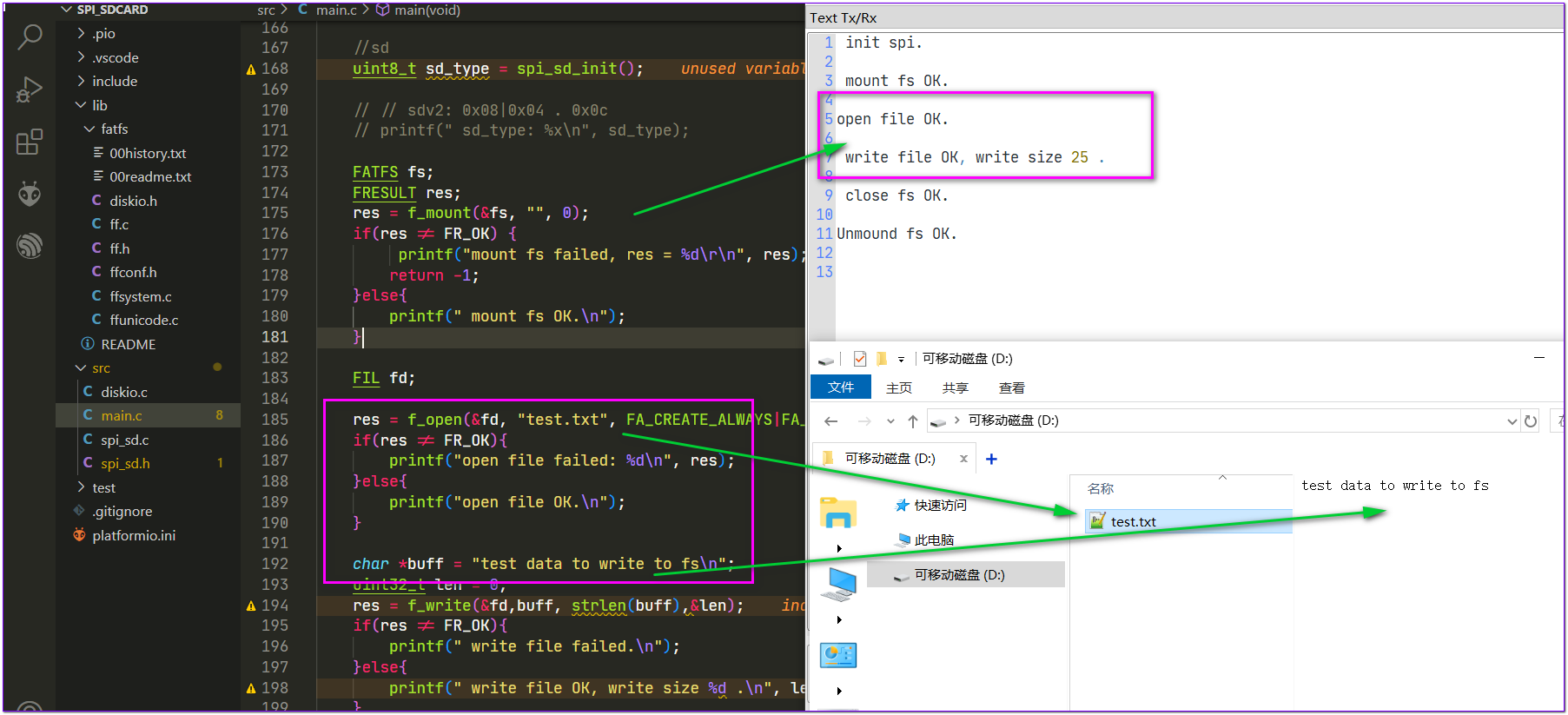
main中测试SD卡挂载、读写;
3 硬件连接
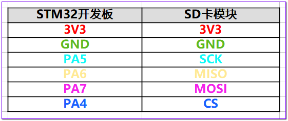
硬件引脚按如下方式连接到SPI1:

4 烧写测试
将程序烧写到开发板后,打开串口,可以看到测试成功,卡中写入文件在电脑显示正确:

完成代码: https://github.com/makerinchina-iot/MonkeyPi-STM32G070-PIO_Libopencm3_example/tree/main/spi_sdcard

评论